Configure Site Mesh Group
Objective
This document presents information and provides instructions on how to configure a Site Mesh Group (SMG) in F5® Distributed Cloud Services. The SMG is used to directly connect F5® Distributed Cloud Console CE sites to other arbitrary CE sites using IPsec. Using the SMG, connectivity between the CE sites is direct and not via the RE sites.
F5® Distributed Cloud Console supports connecting the CE sites in the following modes:
-
Hub-Spoke: A hub site routes traffic between the spoke sites.
-
Full Mesh: All sites have direct connectivity to each other.
Prerequisites
The following prerequisites apply:
-
A valid account is required. If you do not have an account, see Getting Started with Console.
-
Two or more registered CE sites in the enterprise tenant. If you do not have a registered CE Site, see the CE deployment guides.
-
A virtual site. If you do not have a virtual site, see the Create Virtual Site guide.
-
Ensure port 4500 is open on the CE site nodes for ingress traffic.
-
Ensure you are on the latest CRT version for latest available features. See the official releases notes guide for more information. To upgrade your CE, see the Manage CE Site guide.
Restrictions
The following restrictions apply:
-
A spoke can form IPsec tunnels with multiple hubs.
-
A hub site can be a spoke site for another SMG.
-
A site can be member of either a hub group or a spoke group but not both in the same hub-spoke relation.
-
Only IPsec tunnel type is supported.
-
The SMG only works on the SLO network interface.
Configure Hub-Spoke Site Mesh Group
In the Hub-Spoke model, two SMGs are required. One group is for the hub sites and the other is for the spoke sites. The spoke sites establish tunnels with all the hub sites. The hub sites form full mesh connectivity with each other. The sites for each mesh group are selected using the virtual site functionality.
Important: For an SMG with Secure Mesh Site v2 nodes that use public IP addresses, you must define the public IP address on each node by editing its properties.
Step 1: Create SMG for hub site.
- Select the Multi-Cloud Network Connect workspace.
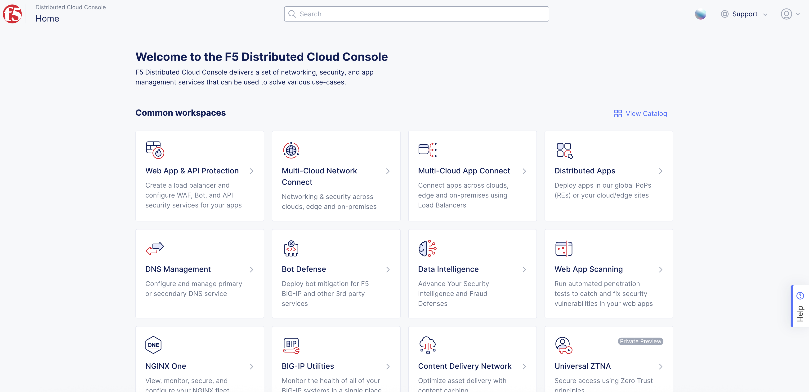
Figure: Homepage
-
Select Manage > Networking > Site Mesh Groups.
-
Select Add Site Mesh Group.
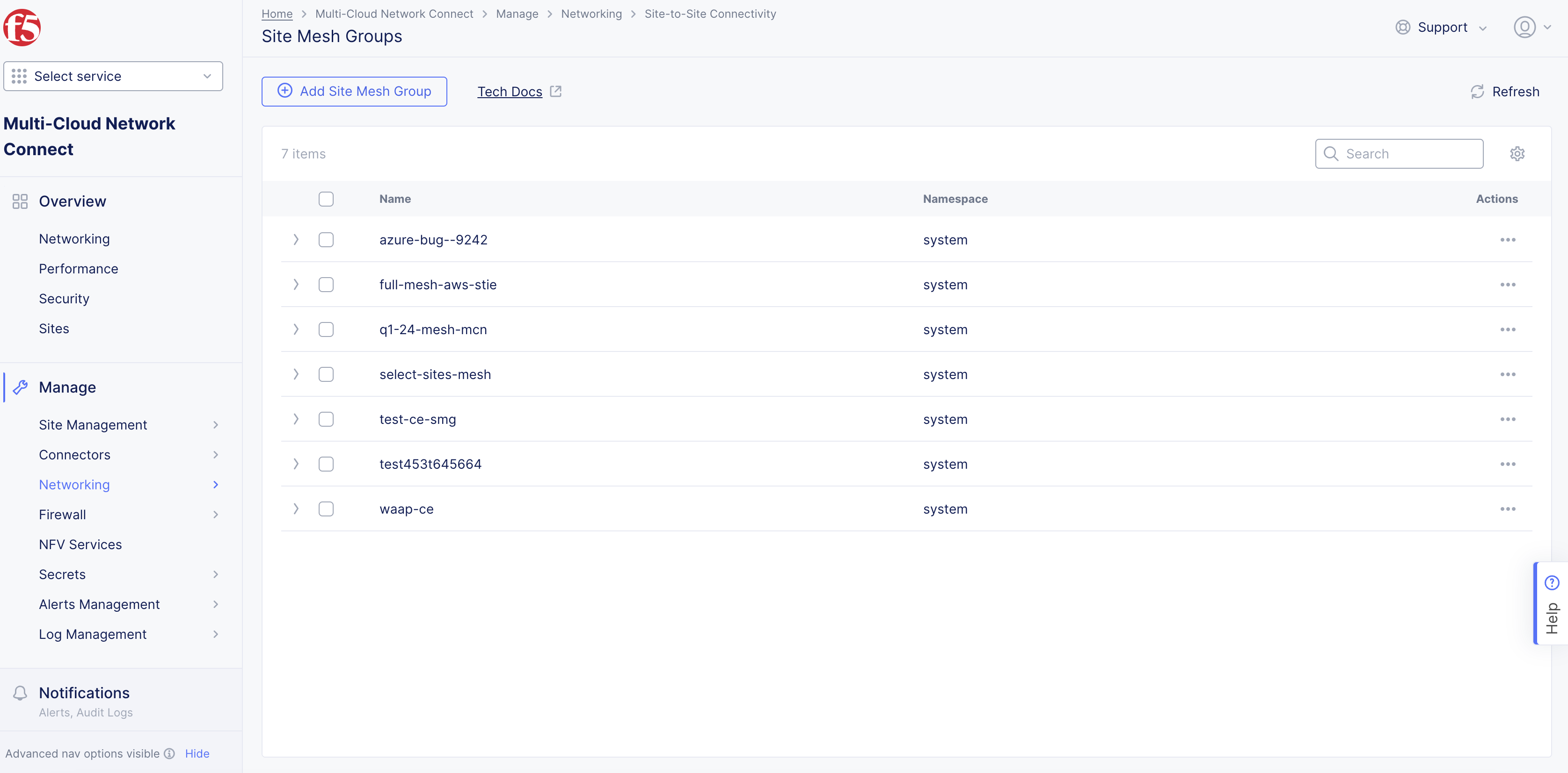
Figure: Navigate to Site Mesh Group
-
Enter Name for your SMG object.
-
From the Virtual Site (Sites in this group) drop-down menu, select the virtual sites that are to be part of this hub group. In a hub-spoke SMG, a hub can have only one site.
-
From the Mesh Choice menu, select Hub.
-
From the RE Fallback menu, confirm what you want to happen if your SMG fails between two CE sites. By default, this option is enabled. This allows the SMG to fall back to the REs so that the routes continue to be learned with the next hop of the REs. If you want to solely depend on your own network data plane redundancy and not failover to the RE, set this option to Disable.
-
From the BFD menu, confirm that you want your SMG to use Bi-directional Forwarding Detection (BFD). By default, this option is enabled. This helps detect link and path failures between the sites in your SMG. You also have the option to change the default settings for the following:
- Transmit Interval: This is the minimum amount of time (typically in milliseconds) the local system wants to wait between sending its own BFD control packets. Transmit interval is in milliseconds. Minimum timer supported is 300 milliseconds.
- Minimum Receive Interval: This is the minimum time interval at which the local system is capable of receiving and processing BFD control packets from its peer. Receive interval is in milliseconds. Minimum timer supported is 300 milliseconds.
- Multiplier: This is the grace period (number of missed packets) before failing. Minimum BFD multiplier is 2.
Important: For the BFD and RE Fallback features, ensure that you are on version crt-20251001-0189. See the official releases notes guide for more information. See the official releases notes guide for more information.
- Select Add Site Mesh Group.
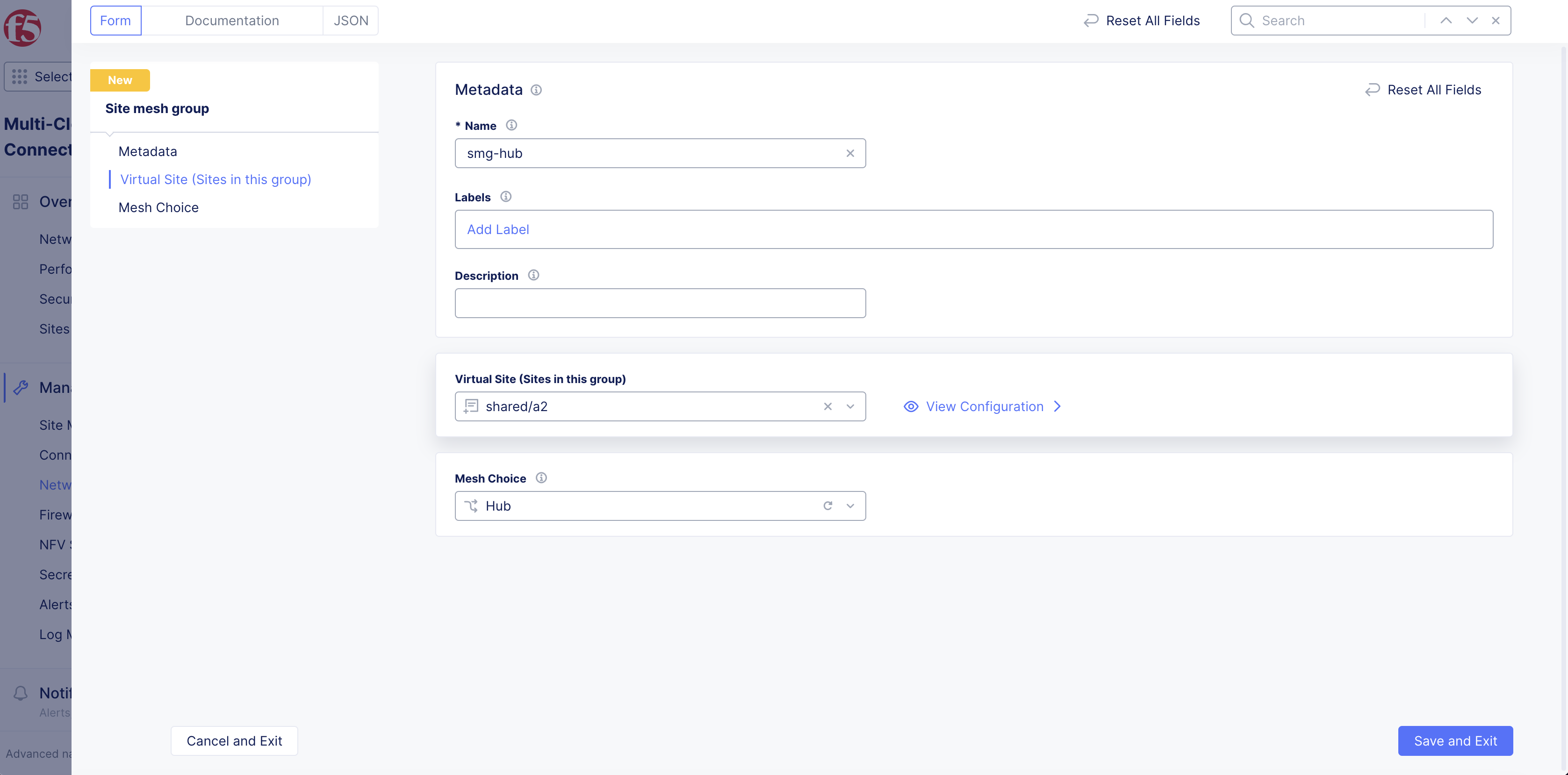
Figure: Hub Site Mesh Group
Step 2: Create SMG for spoke site.
- Select the Multi-Cloud Network Connect workspace.
Figure: Homepage
-
Select Manage > Networking > Site Mesh Groups.
-
Select Add Site Mesh Group.
-
Enter Name for your SMG object.
-
Enter Labels and Description as needed.
-
From the Virtual Site (Sites in this group) drop-down menu, select the virtual sites that are to be part of this spoke group.
-
From the Mesh Choice menu, select Spoke.
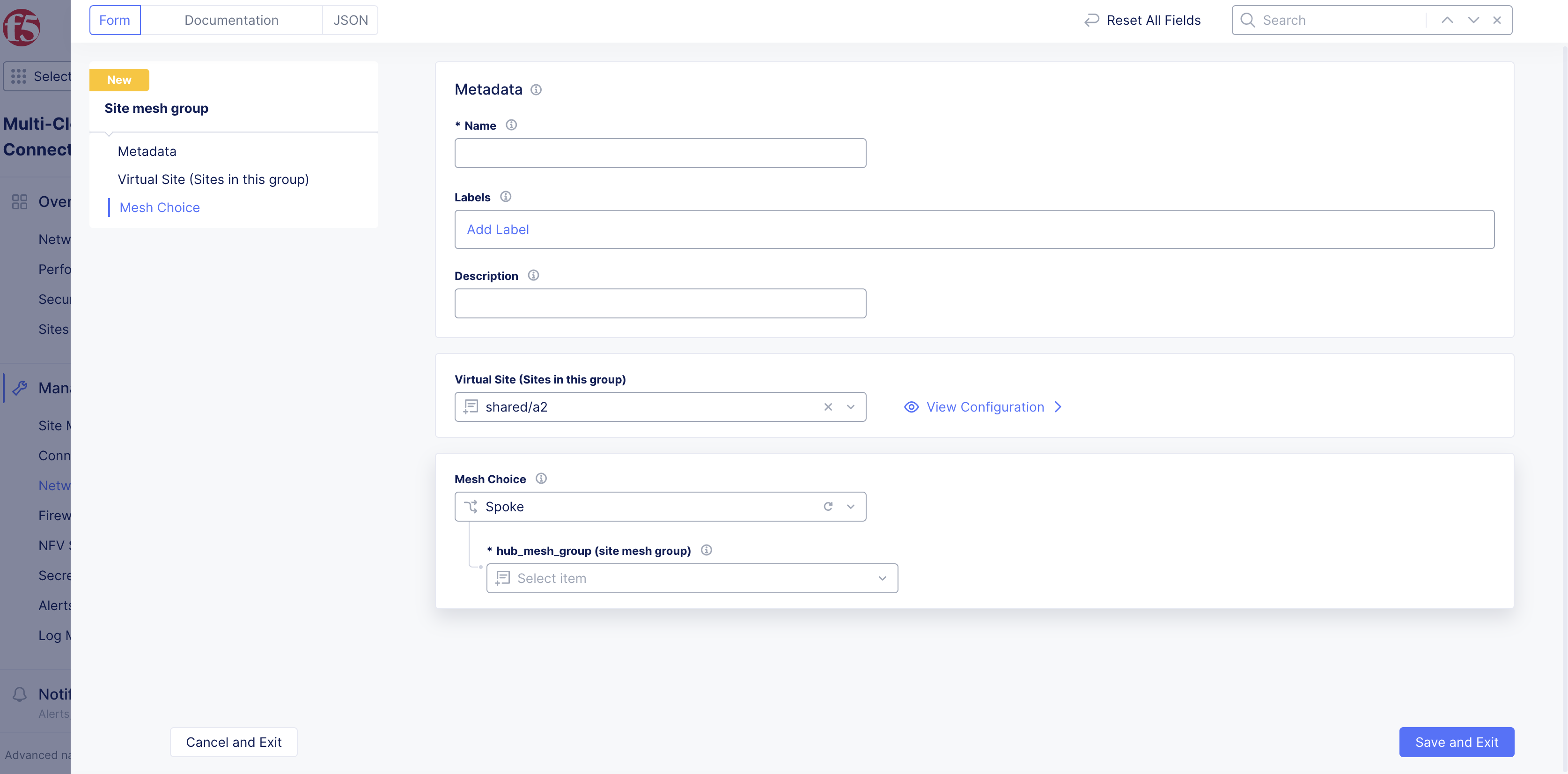
Figure: Spoke Site Mesh Group
-
From the hub_mesh_group (site mesh group) menu, select the hub SMG object created in the previous step.
-
From the RE Fallback menu, confirm what you want to happen if your SMG fails between two CE sites. By default, this option is enabled. This allows the SMG to fall back to the REs so that the routes continue to be learned with the next hop of the REs. If you want to use your own in-network data plane activity, then you can set this option to Disable.
-
From the BFD menu, confirm that you want your SMG to use Bi-directional Forwarding Detection (BFD). By default, this option is enabled. This helps detect link and path failures between the sites in your SMG. You also have the option to change the default settings for the following:
- Transmit Interval: This is the minimum amount of time (typically in milliseconds) the local system wants to wait between sending its own BFD control packets. Transmit interval is in milliseconds. Minimum timer supported is 300 milliseconds.
- Minimum Receive Interval: This is the minimum time interval at which the local system is capable of receiving and processing BFD control packets from its peer. Receive interval is in milliseconds. Minimum timer supported is 300 milliseconds.
- Multiplier: This is the grace period (number of missed packets) before failing. Minimum BFD multiplier is 2.
Important: For the BFD and RE Fallback features, ensure that you are on version crt-20251001-0189. See the official releases notes guide for more information. See the official releases notes guide for more information.
- Select Add Site Mesh Group.
Configure Full Site Mesh Group
Step 1: Create full mesh SMG object.
- Select Multi-Cloud Network Connect.
Figure: Homepage
-
Select Manage > Networking > Site Mesh Groups.
-
Select Add Site Mesh Group.
Figure: Navigate to Site Mesh Group
Step 2: Define sites that are part of the full mesh SMG.
-
Enter a Name for your SMG object.
-
From the Virtual Site (Sites in this group) drop-down menu, select the virtual sites that are to be part of this group.
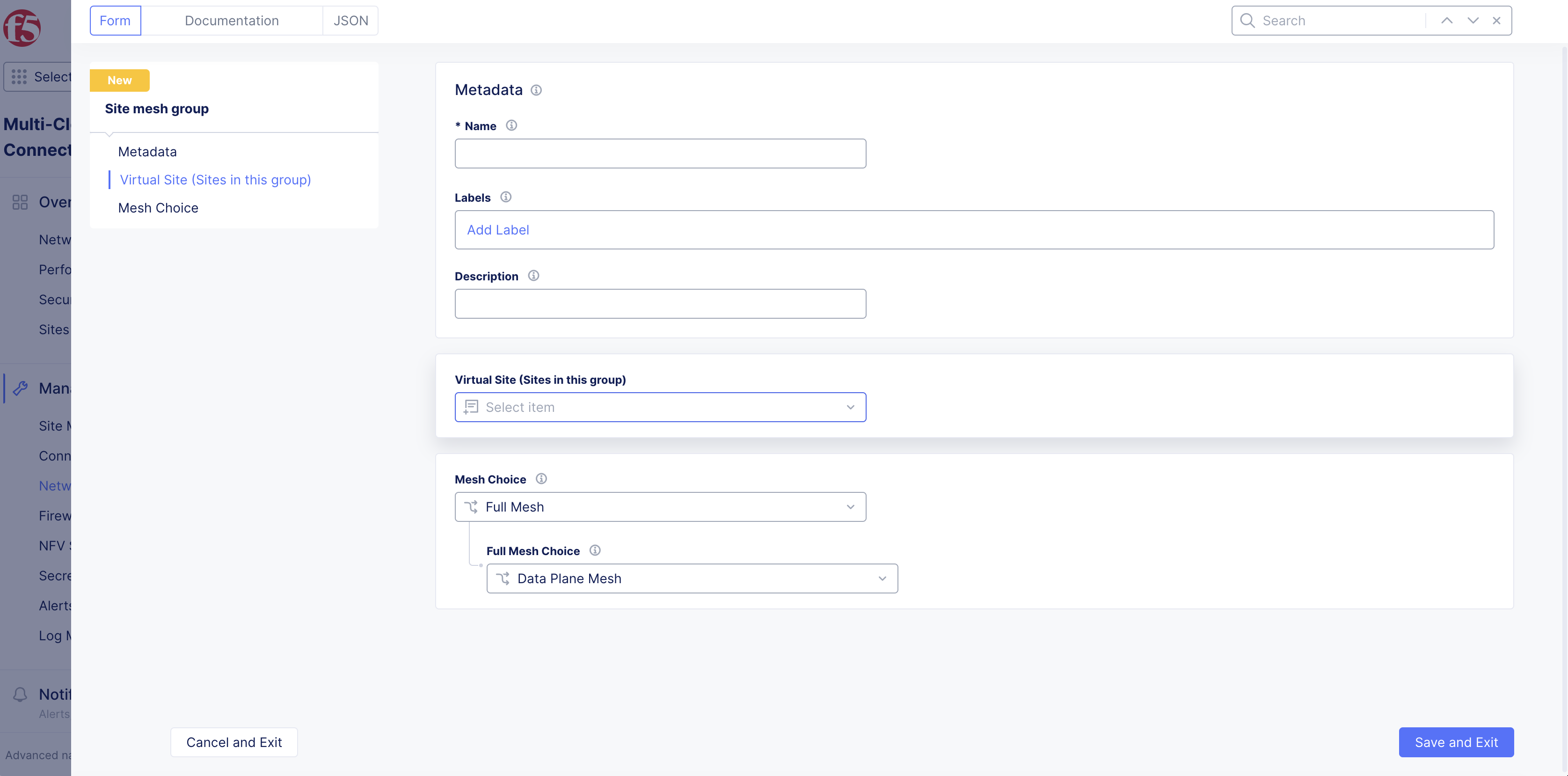
Figure: Virtual Site Site Mesh Group
Step 3: Set SMG type as full mesh.
-
Select Full Mesh from the Mesh Choice drop-down menu.
-
From the Full Mesh Choice menu, select an option from the following:
- Data Plane Mesh: This option extends only the data plane across all participating sites in the SMG.
- Control and Data Plane Mesh: This option extends both the data plane and control plane across all participating sites in the SMG.
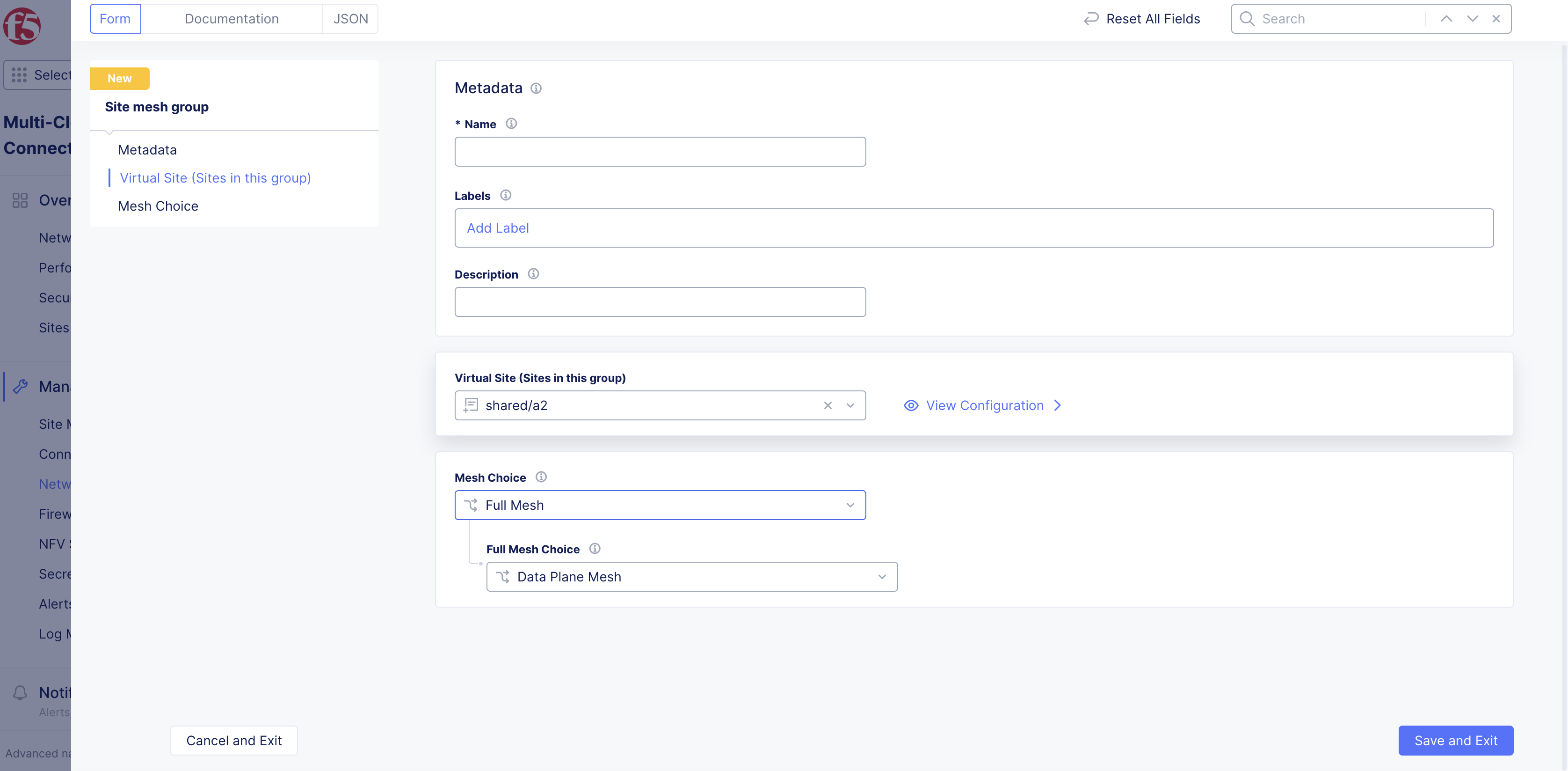
Figure: Full Mesh
Step 4: Complete creating the full mesh SMG.
-
From the RE Fallback menu, confirm what you want to happen if your SMG fails between two CE sites. By default, this option is enabled. This allows the SMG to fall back to the REs so that the routes continue to be learned with the next hop of the REs. If you want to use your own in-network data plane activity, then you can set this option to Disable.
-
From the BFD menu, confirm that you want your SMG to use Bi-directional Forwarding Detection (BFD). By default, this option is enabled. This helps detect link and path failures between the sites in your SMG. You also have the option to change the default settings for the following:
- Transmit Interval: This is the minimum amount of time (typically in milliseconds) the local system wants to wait between sending its own BFD control packets. Transmit interval is in milliseconds. Minimum timer supported is 300 milliseconds.
- Minimum Receive Interval: This is the minimum time interval at which the local system is capable of receiving and processing BFD control packets from its peer. Receive interval is in milliseconds. Minimum timer supported is 300 milliseconds.
- Multiplier: This is the grace period (number of missed packets) before failing. Minimum BFD multiplier is 2.
Important: For the BFD and RE Fallback features, ensure that you are on version crt-20251001-0189. See the official releases notes guide for more information. See the official releases notes guide for more information.
- Select Add Site Mesh Group.
Verify Tunnel Status
The CE dashboard page shows the status of the IPsec tunnel between CEs. Apart from the connected REs, you can also monitor all CE sites that it connects to using IPsec tunnels.
Step 1: Locate CE Site.
-
Select Multi-Cloud Network Connect.
-
Select Infrastructure > Sites.
-
Select your CE Site to open its dashboard.
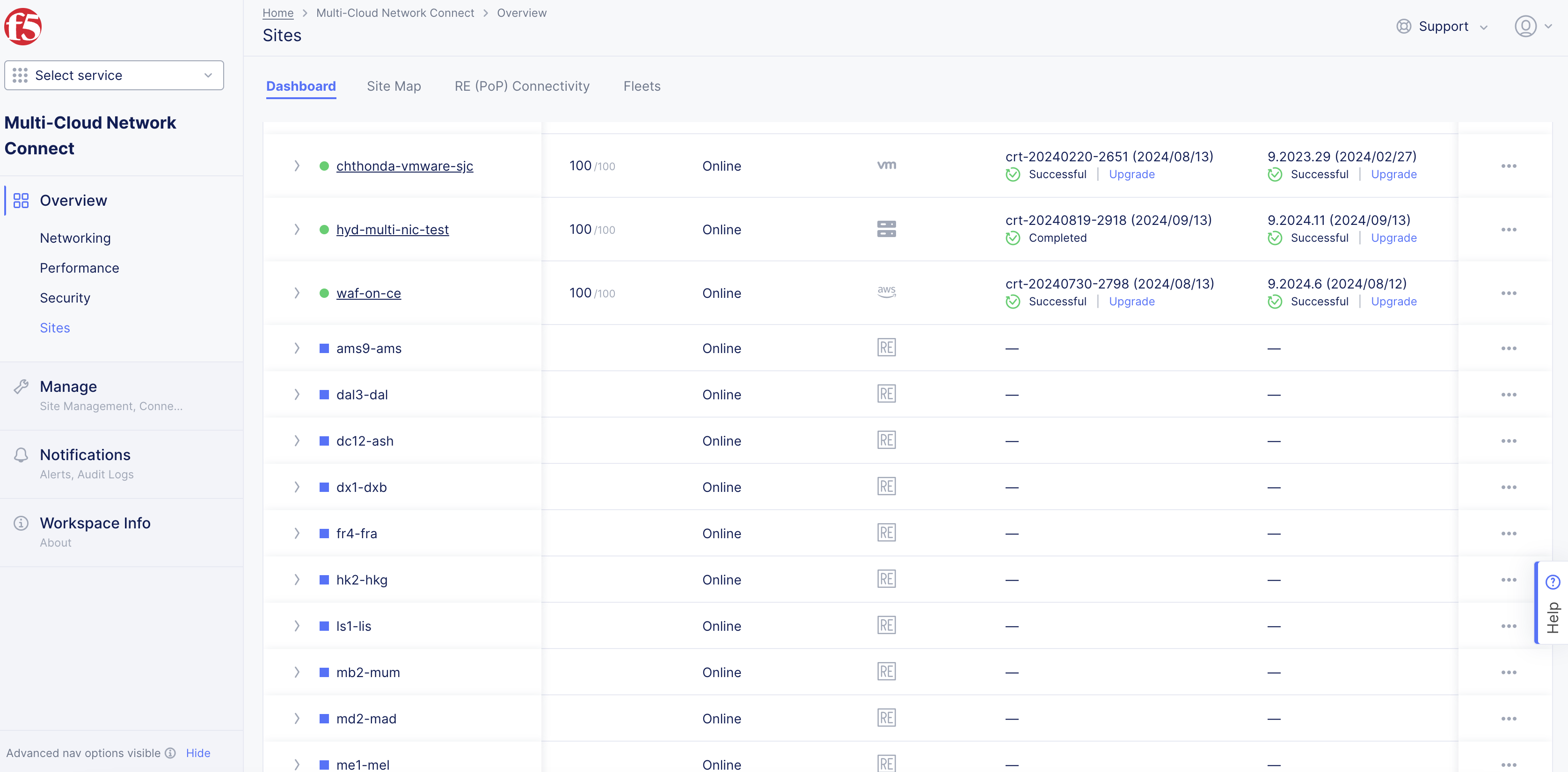
Figure: Site List
Step 2: View status objects in dashboard.
-
Scroll to the bottom of the Dashboard page to the Connectivity section.
-
Select the CE tab.
-
Select the CE object with
Status IDcontaining stringSiteStatusMgr. The JSON format pop-up window opens.
Step 3: Confirm tunnel status in JSON.
-
Check for
site_tunnel_statussection in the displayed JSON. -
Verify that the
statefield of the tunnel toward the other CE isTUNNEL_UP. You can also confirm status using theTunnel statuscolumn withUpvalues.